Useful resources and reference materials for cathodic protection and corrosion control

Cathodic Protection
The corrosion of underground structures is caused by a direct current flowing from one metal surface to another through electrolyte in the adjacent soil. The metal surface discharging the current dissolves metal particles to cause deterioration of the structure. Cathodic protection is a means of stopping the discharge of direct current from the structure or negative (cathodic) metal, by countering with another current from a positive (anodic) metal. This is accomplished by installing anodes in electrical contact with the structure.
- Anodes:
- Galvanic (Sacrificial) – Magnesium, Zinc, and Aluminum
-
Impressed Current – High Silicon Cast Iron, Mixed Metal Oxide, Graphite, Platinum
- Rectifier:
- Air Cooled, Oil Cooled, Custom
- Cable/Wire, Connectors, Wire Splice Kits, & Fittings
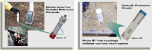
- Test Stations, Reference Electrodes, & Testing Equipment
Coatings & Wraps
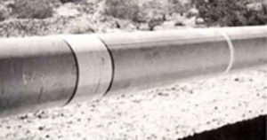
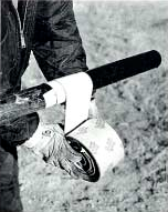
Stuart Steel offers a wide range of coatings, wraps, and application equipment for corrosion control. These products include: epoxies, hot-applied tar coatings, heat-shrinkable sleeves, cold-applied tapes, mastics, petrolatum and Stuart Rock Stop™. The Stuart Wrapster™, a pipe-wrapping machine developed in 1968, is specifically designed for applying Stuart Super Wrap and other hot or cold-applied plasticized tapes.


Electrical Isolation
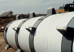
Stuart Steel isolation products include dielectric unions and flange insulation kits with gaskets, sleeves and washers. We offer a variety of products to seal and separate the carrier pipe from the casing. They include Stuart Casing Seal Kits, rubber link seals, spacers and casing fillers. tape, transition fittings, couplings and tools associated with corrosion control.
Instruments & Accessories
Electrical metering and instrumentation products include potential meters, reference cells, soil resistance instruments, holiday detectors, pipe locators, and other field monitoring devices.
Stuart Steel Accessories include pipeline pigs for internal cleaning, pipeline marking tape, transition fittings, couplings and tools associated with corrosion control.

Electromotive Force Series
| Anodic End | Electrode Reaction | Standard Electrode Potential, E (Volts), 25 °C |
| Magnesium | Mg2+ + 2e | -2.34 |
| Aluminum | Al3+ + 3e | -1.67 |
| Zinc | Zn3+ + 2e | -0.076 * |
* Anodic, base or electronegative
Cable and Wire Chart
| AWG | Diameter in Inches | Circular Mills | Cross Sectional Area in Sq. Inches | LB/1000 Ft. | |
| Copper | Aluminum | ||||
| 0000 | 0.46 | 211600 | 0.1662 | 640.5 | 194.7 |
| 000 | 0.4096 | 167800 | 0.1318 | 507.8 | 154.4 |
| 00 | 0.3648 | 133100 | 0.1045 | 402.8 | 122.4 |
| 0 | 0.3249 | 105600 | 0.08291 | 319.5 | 97.13 |
| 1 | 0.2893 | 83690 | 0.06573 | 253.3 | 77 |
| 2 | 0.2576 | 66360 | 0.05212 | 200.9 | 61.07 |
| 3 | 0.2294 | 52620 | 0.04133 | 159.3 | 48.43 |
| 4 | 0.2043 | 41740 | 0.03278 | 126.3 | 38.39 |
| 5 | 0.1819 | 33090 | 0.02599 | 100.2 | 30.46 |
| 6 | 0.162 | 26240 | 0.02061 | 79.4 | 24.15 |
| 7 | 0.1443 | 20820 | 0.01635 | 63 | 19.16 |
| 8 | 0.1285 | 16510 | 0.01297 | 49 | 15.19 |
| 9 | 0.1144 | 13090 | 0.01028 | 39.6 | 12.04 |
| 10 | 0.1019 | 10380 | 0.00816 | 31.4 | 9.55 |
| 11 | 0.0907 | 8230 | 0.00646 | 24.9 | 7.57 |
| 12 | 0.0808 | 6530 | 0.00513 | 19.8 | 6.02 |
| 13 | 0.072 | 5180 | 0.00407 | 15.7 | 4.77 |
| 14 | 0.0641 | 4110 | 0.00323 | 12.4 | |
Resistance and Output Currents of Sacrificial Anodes
| Nominal Weight (lb) | Anode Package Size (in) | Soil Restistivity (ohms) | Anode Resistance (ohms) | Current output and est. life for structure Potential (volts): | ||
| 0.3 (mA) (yrs) | 0.5 (mA) (yrs) | 0.85 (mA) (yrs) | ||||
| Standard magnesium – AZ63 (Hi alloy) – solution potetial – 1.55 V | ||||||
| 17 | 22×7 | 5000 | 23 | 54 19 | 46 21 | 30 33 |
| 10000 | 46 | 27 37 | 23 15 | |||
| 20000 | 92 | 14 11 | 8 | |||
| 32 | 26×8.5 | 20000 | 7.7 | 162 12 | 136 15 | 91 22 |
| 5000 | 19 | 66 30 | 55 36 | 37 | ||
| 10000 | 38 | 33 60 | 28 18 | |||
| 50 | 22×10 | 2000 | 7.1 | 176 17 | 147 20 | 98 31 |
| 5000 | 18 | 69 43 | 58 39 | |||
| 10000 | 36 | 35 29 | 19 | |||
| High – potential magnesium – solution potential – 1.73 V | ||||||
| 17 | 38×6 | 5000 | 19 | 75 13 | 65 15 | 46 22 |
| 10000 | 39 | 37 32 | 31 23 | 23 43 | ||
| 20000 | 18 | 16 11 | ||||
| 48 | 34×8 | 2000 | 7.2 | 199 | ||
Pipe Coverage Data Sheet
| Nominal Size (Inches) |
Actual Pipe (Inches) | Pipe Surface Square Feet (1000 ft.) | Tape Width (Inches) | Minimum Tape Overlap (Inches) | Tape Required for 1000 Lineal Ft. Pipe (Squares) |
| 0.5 | 0.84 | 220 | 2 | 0.25 | 2.52 |
| 0.75 | 1.05 | 275 | 2 | 0.25 | 3.14 |
| 1 | 1.315 | 344 | 2 | 0.25 | 3.94 |
| 1.25 | 1.66 | 435 | 2 | 0.25 | 4.98 |
| 1.5 | 1.9 | 497 | 2 | 0.25 | 5.68 |
| 2 | 2.375 | 622 | 4 | 0.375 | 6.87 |
| 2.5 | 2.875 | 753 | 4 | 0.375 | 8.31 |
| 3 | 3.5 | 916 | 4 | 0.375 | 10.1 |
| 3.5 | 4 | 1047 | 4 | 0.375 | 11.6 |
| 4 | 4.5 | 1178 | 6 | 0.5 | 12.9 |
| 4.5 | 5 | 1309 | 6 | 0.5 | 14.3 |
| 5 | 5.563 | 1456 | 6 | 0.5 | 15.9 |
| 6 | 6.625 | 1734 | 6 | 0.5 | 19 |
| 8 | 8.625 | 2258 | 9 | 0.5 | 24 |
| 10 | 10.75 | 2814 | 9 | 0.5 | 29.8 |
| 12 | 12.75 | 3338 | 9 | 0.5 | 35.6 |
| 14 | 14 | 3665 | 12 | 0.75 | 39.1 |
| 16 | 16 | 4189 | 12 | 0.75 | 44.7 |
| 18 | 18 | 4713 | 18 | 1 | 50 |
| 20 | 20 | 5236 | 18 | 1 | 55.5 |
| 22 | 22 | 5760 | 18 | 1 | 61 |
| 24 | 24 | 6283 | 18 | 1 | 66.5 |
| 26 | 26 | 6807 | 18 | 1 | 72.1 |
| 28 | 28 | 7330 | 18 | 1 | 77.6 |
| 30 | 30 | 7854 | 18 | 1 | 83.2 |
| 32 | 32 | 8378 | 18 | 1 | 88.7 |
| 34 | 34 | 8901 | 18 | 1 | 94.3 |
| 36 | 36 | 9425 | 18 | 1 | 99.8 |
| 42 | 42 | 10990 | 18 | 1 | 116.4 |
| 48 | 48 | 12560 | 18 | 1 | 133 |
| 54 | 54 | 14139 | 18 | 1 | 149.7 |
| 60 | 60 | 15710 | 18 | 1 | 166.3 |
Bolts
| Nom Dia | Flange OD | Flange Thickness Dia. | B.C. | Bolt Hole Dia. | Bold Dia. | No. of Bolts | Length of Bolt | Thread Length |
| 6 | 11 | 1 | 9.5 | 0.875 | 0.75 | 8 | 4 | 1.75 |
| 8 | 13.5 | 1.125 | 11.75 | 0.875 | 0.75 | 8 | 4 | 1.75 |
| 12 | 19 | 1.25 | 17 | 1 | 0.875 | 12 | 4.5 | 2 |
| 16 | 23.5 | 1.4375 | 21.25 | 1.125 | 1 | 16 | 5 | 2.25 |
| 20 | 27.5 | 1.6875 | 25 | 1.25 | 1.125 | 20 | 5.5 | 2.5 |
| 24 | 32 | 1.875 | 29.5 | 1.375 | 1.25 | 20 | 6 | 2.75 |
| 30 | 38.75 | 2.125 | 36 | 1.375 | 1.25 | 28 | 6.5 | 3 |
| 36 | 46 | 2.375 | 42.75 | 1.625 | 1.5 | 32 | 7.5 | 3.5 |
| 48 | 59.5 | 2.75 | 56 | 1.625 | 1.5 | 44 | 8 | 3.5 |
| 60 | 73 | 3.125 | 69.25 | 1.875 | 1.75 | 52 | 9 | 4 |
| 66 | 80 | 3.375 | 76 | 1.875 | 1.75 | 52 | 9.5 | 4 |
| 72 | 86.5 | 3.5 | 82.5 | 1.875 | 1.75 | 60 | 10 | 4 |
A Galvanic Series of Certain Metals and Alloys Arranged In Order of Corrosivity
| ANODIC (Least Noble) End Material |
| Magnesium |
| Magnesium alloys |
| Zinc |
| Aluminum 25 |
| Cadmium |
| Aluminum 17ST |
| Steel or iron |
| Cast iron |
| Chromium-iron (active) |
| Ni-Resist |
| 18-8 Chromium-nickel-iron (active) |
| 18-8-3 Chromium-nickel-molybdenum-iron (active) |
| Lead-tin solders |
| Lead |
| Tin |
| Nickel (active) |
| Inconel (active) |
| Hastelloy C (active) |
| Brasses |
| Copper |
| Bronzes |
| Copper-nickel alloys |
| Monel |
| Silver Solder |
| Nickel (passive) |
| Inconel (passive) |
| Chromium-iron (passive) |
| 18-8 Chromium-nickel iron (passive) |
| 18-8-3 Chromium-nickel-molybdenum-iron (passive) |
| Hastelloy C (passive) |
| Silver |
| Carbon and graphite |
| Platinum |
| Gold |
| CATHODIC (Most Noble) |
Electrochemical
Equivalent of Metals
| Material | Theoretical Pounds of Metal Removed Per Ampere Year |
| Magnesium | 8.76 |
| Aluminum | 6.47 |
| Zinc | 23.5 |
| Chromium | 12.5 |
| Iron | 20.1 |
| Cadmium | 40.5 |
| Cobalt | 21.2 |
| Nickel | 21.1 |
| Tin | 42.7 |
| Lead | 74.2 |
| Copper (Cu2+) | 22.8 |
| Copper (Cu+) | 45.7 |
| Carbon (C+) | 4.23 |
| Carbon (C4+) | 2.16 |
Diamond Rockstop Coverage Table
| Coverage Information Stuart Diamond Rockstop | ||||||||||||||||
| Pipe Diameter” | 6 | 8 | 10 | 12 | 14 | 16 | 18 | 20 | 22 | 24 | 26 | 30 | 36 | 42 | 48 | |
| Rolls 500 sqft | 4.7 | 6.3 | 7.9 | 9.4 | 11.0 | 12.6 | 14.1 | 15.7 | 17.3 | 18.8 | 20.4 | 23.6 | 28.3 | 33.0 | 37.7 | |
