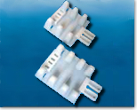
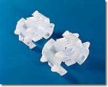
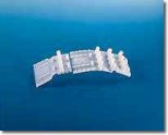
Insulators/Spacers are required to separate casing and carrier pipes with the following criteria:
- Must ensure electrical insulation between the two pipes
- Permanently prevent bells from sliding or resting on casing pipe
- Must fasten tightly on the carrier pipe to ensure no horizontal movement during insertion
- Must be made of materials which do not conduct electricity and are permanently resistant to chemical corrosion
- Must be resistant to both mechanical and thermal shocks and stresses particularly during installation
RACI Spacers have met the above requirements with the following advantages over the standard skid and strap application and other models of manufactured spacers.
- Spacers are manufactured entirely out of high density polyethylene with NO METAL bolts or attachments required.
- Spacers are quickly and easily assembled by manually fitting elements one into the other.
- Tooth insertion method allows on site adjustment to fit a wide range of pipe diameters and coatings.
- Spacers slide into casing with ease.
- Spacers maintain continual long term support for the carrier pipe and its contents.
- Spacers provide constant projections around the entire circumference of the carrier pipe.
- Spacers provide long term corrosion protection.
- Spacers can be installed on coated or plain concrete, ductile iron, plastic and steel pipe.
The spacers are divided into six groups which address a wide range of pipe sizes and weights. Within each grouping there are varying support heights that allow the spacer to clear bell joints, flanges, couplings, and other jointing methods. These heights range from .78 inches to 5.11 inches (20 – 130 mm).
Spacing RACI Spacers
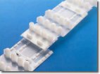 The spacing of the rings must ensure that the carrier pipe is fully supported throughout its length. To ensure against the effects of differential loading at the entrance and exit points of the casing, two rings are used at the beginning and end of the each casing, regardless of pipe size or length.
Selection Guidelines
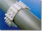 The selection of spacer type depends on the following dimensions:
- exact carrier pipe O.D.
- exact bell, flange or coupling O.D.
- exact casing Pipe I.D.
- clearance desired between casing and carrier pipe
- length of application and linear weight of filled carrier pipe
With the above information and using the charts from Product Details, the type and number of spacer elements required for each ring and how far they will be spaced can be determined.
Ring Assembly
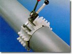
- In cases where the carrier pipe is plastic, the contact zone between the pipe and spacer should be taped to ensure a textured contact area. Double backed tape should be either self amalgamating or bituminous.
- Insert the male butt strap three teeth into the slotted female end of the next element.. Continue until you have formed a chain of the required number of elements.
- To complete the ring, wrap the spacer loosely around the pipe and complete the last linking by hand.
- Pull each of the butt straps together by hand until the spacer is tightened uniformly on the pipe.
- The final tightening is done using the special clamping tool for the spacer type.
Specification Suggestions for RACI Casing Spacers
Casing spacers shall be used to install carrier pipe inside the encasement pipe. To provide support around the periphery of the pipe should the pipe twist as it is pushed through the casing. The spacers shall be of a projection type that has a minimum number of projections around the circumference totaling the number of diameter inches. For example, 8″ pipe shall have a minimum of 8 projections and 18″ pipe shall have a minimum of 18 projections.
Casing spacers shall use double backed tape, provided with the spacers, to fasten tightly onto the carrier pipe so that the spacers do not move during installation. Installation instructions shall be provided with each shipment. Casing spacers shall have a span of 10 feet to 6-1/2 feet dependent on the total load anticipated with the pipe full of liquid. On sewer pipe, the maximum span should be 7 feet to prevent sagging of the carrier pipe. The maximum load shall not exceed the load limits per spacer listed in the brochure. These values in the brochure include conservative safety factors for class spacer used. Spacers shall have minimum height that clears the pipe bell or as otherwise indicated on plans.
Casing spacers shall be projection type totally non-metallic spacers constructed of preformed sections of high-density polyethylene. Spacers shall be ISO 9002 certified for strength and quality. Projection type spacers shall be RACI type spacers along with wrap around end seal made of 1/8″ think rubber with stainless steel bands.
RACI Spacer Types
S / T
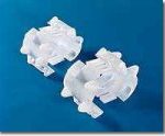
F / G
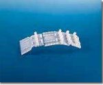
M / N
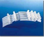
E / H
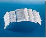
P / Q

A / B
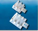
Spacer Specification Charts
Spacers by carrier pipe outer diameter
| Type | Units per ring | O.D. Min in. | O.D Max in. | O.D. Min mm. | O.D Max mm. | Ring Spacing ft. | Ring Spacing m. | Max. Load lbs. | Max Load kgs. |
|---|---|---|---|---|---|---|---|---|---|
| S | 1 | 1.18 | 1.38 | 30 | 35 | 5 | 1.5 | 250 | 110 |
| T | 1 | 1.5 | 1.69 | 38 | 43 | 5 | 1.5 | 250 | 110 |
| B | 2 | 2.17 | 2.52 | 55 | 64 | 6.5 | 2 | 397 | 180 |
| A | 1 | 2.36 | 2.76 | 60 | 70 | 6.5 | 2 | 397 | 180 |
| S | 2 | 2.36 | 2.76 | 60 | 70 | 5 | 1.5 | 250 | 110 |
| B | 1 | 2.36 | 2.76 | 60 | 70 | 6.5 | 2 | 397 | 180 |
| S | 1 | 2.68 | 2.99 | 68 | 76 | 5 | 1.5 | 250 | 110 |
| T | 1 | 2.68 | 2.99 | 68 | 76 | 5 | 1.5 | 250 | 110 |
| A | 2 | 2.68 | 3.03 | 68 | 77 | 6.5 | 2 | 397 | 180 |
| T | 2 | 3.03 | 3.39 | 77 | 86 | 6-10 | 1.5 | 250 | 110 |
| B | 3 | 3.35 | 3.86 | 85 | 98 | 6.5 | 2 | 397 | 180 |
| S | 3 | 3.54 | 4.13 | 90 | 105 | 6-10 | 1.5 | 250 | 110 |
| B | 2 | 3.54 | 4.17 | 90 | 106 | 5 | 2 | 397 | 180 |
| A | 1 | 3.54 | 4.17 | 90 | 106 | 5 | 2 | 397 | 180 |
| G | 1 | 3.62 | 4.53 | 92 | 115 | 6-10 | 1.8-3.0 | 1102 | 500 |
| F | 1 | 3.62 | 4.53 | 92 | 115 | 6-10 | 1.8-3.0 | 1102 | 500 |
| A | 3 | 3.86 | 4.57 | 98 | 116 | 5 | 1.5 | 397 | 180 |
| S | 1 | 4.17 | 4.72 | 106 | 120 | 6-10 | 1.5 | 250 | 110 |
| T | 2 | 4.17 | 4.72 | 106 | 120 | 6-10 | 1.5 | 250 | 110 |
| B | 4 | 4.65 | 5.2 | 118 | 132 | 5 | 1.5 | 397 | 180 |
| S | 4 | 4.76 | 5.43 | 121 | 138 | 6-10 | 1.5 | 250 | 110 |
| B | 3 | 4.92 | 5.51 | 125 | 140 | 5 | 1.5 | 397 | 180 |
| A | 1 | 4.92 | 5.51 | 125 | 140 | 5 | 1.5 | 397 | 180 |
| F | 2 | 4.57 | 5.98 | 116 | 152 | 6-10 | 1.8-3.0 | 1102 | 500 |
| S | 2 | 5.47 | 6.06 | 139 | 154 | 6-10 | 1.5 | 250 | 110 |
| T | 2 | 5.47 | 6.06 | 139 | 154 | 6-10 | 1.5 | 250 | 110 |
| A | 4 | 5.51 | 6.22 | 140 | 158 | 5 | 1.5 | 397 | 180 |
| S | 1 | 6.1 | 6.46 | 155 | 164 | 6-10 | 1.5 | 250 | 110 |
| T | 3 | 6.1 | 6.46 | 155 | 164 | 6-10 | 1.5 | 250 | 110 |
| N | 1 | 5.63 | 6.61 | 143 | 168 | 6-10 | 1.8-3.0 | 2865 | 1300 |
| Q | 1 | 5.63 | 6.61 | 143 | 168 | 6-10 | 1.8-3.0 | 1213 | 550 |
| P | 1 | 5.63 | 6.61 | 143 | 168 | 6-10 | 1.8-3.0 | 1213 | 550 |
| M | 1 | 5.63 | 6.61 | 143 | 168 | 6-10 | 1.8-3.0 | 2865 | 1300 |
| B | 3 | 6.22 | 7.09 | 158 | 180 | 5 | 1.5 | 397 | 180 |
| A | 2 | 6.22 | 7.09 | 158 | 180 | 5 | 1.5 | 397 | 180 |
| F | 2 | 6.02 | 7.4 | 153 | 188 | 6-10 | 1.8-3.0 | 1102 | 500 |
| G | 1 | 6.02 | 7.4 | 153 | 188 | 6-10 | 1.8-3.0 | 1102 | 500 |
| A | 5 | 7.01 | 7.87 | 178 | 200 | 5 | 1.5 | 397 | 180 |
| M | 2 | 6.65 | 7.91 | 169 | 201 | 6-10 | 1.8-3.0 | 2865 | 1300 |
| P | 2 | 6.65 | 7.91 | 169 | 201 | 6-10 | 1.8-3.0 | 1213 | 550 |
| F | 3 | 7.44 | 8.34 | 189 | 224 | 6-10 | 1.8-3.0 | 1102 | 500 |
| N | 2 | 7.95 | 8.94 | 202 | 227 | 6-10 | 1.8-3.0 | 2865 | 1300 |
| M | 1 | 7.95 | 8.94 | 202 | 227 | 6-10 | 1.8-3.0 | 2865 | 1300 |
| Q | 2 | 7.95 | 8.94 | 202 | 227 | 6-10 | 1.8-3.0 | 1213 | 550 |
| P | 1 | 7.95 | 8.94 | 202 | 227 | 6-10 | 1.8-3.0 | 1213 | 550 |
| B | 7 | 7.87 | 9.45 | 200 | 240 | 5 | 1.5 | 397 | 180 |
| A | 6 | 8.46 | 9.53 | 215 | 242 | 5 | 1.5 | 397 | 180 |
| Q | 1 | 8.98 | 9.92 | 228 | 252 | 6-10 | 1.8-3.0 | 1213 | 550 |
| M | 2 | 8.98 | 9.92 | 228 | 252 | 6-10 | 1.8-3.0 | 2865 | 1300 |
| P | 2 | 8.98 | 9.92 | 228 | 252 | 6-10 | 1.8-3.0 | 1213 | 550 |
| N | 1 | 8.98 | 9.92 | 228 | 252 | 6-10 | 1.8-3.0 | 2865 | 1300 |
| G | 1 | 8.35 | 10.24 | 225 | 260 | 6-10 | 1.8-3.0 | 1102 | 500 |
| F | 3 | 8.35 | 10.24 | 225 | 260 | 6-10 | 1.8-3.0 | 1102 | 500 |
| H | 1 | 8.7 | 10.55 | 221 | 268 | 6 | 1.8 | 5952 | 2700 |
| E | 2 | 8.7 | 10.55 | 221 | 268 | 6 | 1.8 | 5952 | 2700 |
| A | 6 | 9.41 | 10.71 | 239 | 272 | 5 | 1.5 | 397 | 180 |
| B | 1 | 9.41 | 10.71 | 239 | 272 | 5 | 1.5 | 397 | 180 |
| A | 7 | 9.65 | 11.06 | 245 | 281 | 5 | 1 | 397 | 180 |
| M | 3 | 9.96 | 11.26 | 253 | 286 | 6-10 | 1.8-3.0 | 2865 | 1300 |
| P | 3 | 9.96 | 11.26 | 253 | 286 | 6-10 | 1.8-3.0 | 1213 | 550 |
| F | 4 | 10.28 | 11.61 | 261 | 295 | 6-10 | 1.8-3.0 | 1102 | 500 |
| P | 2 | 11.3 | 12.24 | 287 | 311 | 6-10 | 1.8-3.0 | 1213 | 550 |
| M | 2 | 11.3 | 12.24 | 287 | 311 | 6-10 | 1.8-3.0 | 2865 | 1300 |
| N | 2 | 11.3 | 12.24 | 287 | 311 | 6-10 | 1.8-3.0 | 2865 | 1300 |
| Q | 2 | 11.3 | 12.24 | 287 | 311 | 6-10 | 1.8-3.0 | 1213 | 550 |
| F | 4 | 11.65 | 12.32 | 296 | 313 | 6-10 | 1.8-3.0 | 1102 | 500 |
| G | 1 | 11.65 | 12.32 | 296 | 313 | 6-10 | 1.8-3.0 | 1102 | 500 |
| E | 3 | 10.59 | 12.6 | 269 | 320 | 6 | 1.8 | 5952 | 2700 |
| Q | 1 | 12.28 | 13.27 | 312 | 337 | 6-10 | 1.8-3.0 | 1213 | 550 |
| N | 1 | 12.28 | 13.27 | 312 | 337 | 6-10 | 1.8-3.0 | 2865 | 1300 |
| P | 3 | 12.28 | 13.27 | 312 | 337 | 6-10 | 1.8-3.0 | 1213 | 550 |
| M | 3 | 12.28 | 13.27 | 312 | 337 | 6-10 | 1.8-3.0 | 2865 | 1300 |
| E | 3 | 12.64 | 14.41 | 321 | 366 | 6 | 1.8 | 5952 | 2700 |
| H | 1 | 12.64 | 14.41 | 321 | 366 | 6 | 1.8 | 5952 | 2700 |
| F | 5 | 12.36 | 14.8 | 314 | 376 | 6-10 | 1.8-3.0 | 1102 | 500 |
| P | 4 | 13.31 | 15.55 | 338 | 395 | 6-10 | 1.8-3.0 | 1213 | 550 |
| M | 4 | 13.31 | 15.55 | 338 | 395 | 6-10 | 1.8-3.0 | 2865 | 1300 |
| E | 4 | 14.45 | 16.54 | 367 | 420 | 6 | 1.8 | 5952 | 2700 |
| Q | 1 | 15.59 | 16.57 | 396 | 421 | 6-10 | 1.8-3.0 | 1213 | 550 |
| P | 4 | 15.59 | 16.57 | 396 | 421 | 6-10 | 1.8-3.0 | 1213 | 550 |
| N | 1 | 15.59 | 16.57 | 396 | 421 | 6-10 | 1.8-3.0 | 2865 | 1300 |
| M | 4 | 15.59 | 16.57 | 396 | 421 | 6-10 | 1.8-3.0 | 2865 | 1300 |
| F | 6 | 14.84 | 17.56 | 377 | 446 | 6-10 | 1.8-3.0 | 1102 | 500 |
| H | 1 | 16.57 | 18.31 | 421 | 465 | 6 | 1.8 | 5952 | 2700 |
| E | 4 | 16.57 | 18.31 | 421 | 465 | 6 | 1.8 | 5952 | 2700 |
| P | 5 | 16.61 | 19.88 | 422 | 505 | 6-10 | 1.8-3.0 | 1213 | 550 |
| M | 5 | 16.61 | 19.88 | 422 | 505 | 6-10 | 1.8-3.0 | 2865 | 1300 |
| F | 7 | 17.6 | 20.79 | 447 | 528 | 6-10 | 1.8-3.0 | 1102 | 500 |
| E | 5 | 18.35 | 20.87 | 466 | 530 | 6 | 1.8 | 5952 | 2700 |
| M | 6 | 19.92 | 23.23 | 506 | 590 | 4-10 | 1.5-3.0 | 2865 | 1300 |
| P | 6 | 19.92 | 23.23 | 506 | 590 | 4.9 | 1.5 | 1213 | 550 |
| E | 6 | 20.91 | 24.8 | 531 | 630 | 6 | 1.8 | 5952 | 2700 |
| M | 7 | 23.27 | 26.54 | 591 | 674 | 4-10 | 1.5-3.0 | 2865 | 1300 |
| E | 7 | 24.84 | 28.74 | 631 | 730 | 6 | 1.8 | 5952 | 2700 |
| M | 8 | 26.57 | 29.88 | 675 | 759 | 4.6 | 1.5 | 2865 | 1300 |
| E | 8 | 28.78 | 32.68 | 731 | 830 | 6 | 1.8 | 5952 | 2700 |
| M | 9 | 29.92 | 32.68 | 760 | 830 | 4.6 | 1.5 | 2865 | 1300 |
| E | 9 | 32.72 | 36.61 | 831 | 930 | 6 | 1.8 | 5952 | 2700 |
| E | 10 | 36.65 | 40.55 | 931 | 1030 | 4-10 | 1.5-3.0 | 5952 | 2700 |
| E | 11 | 40.59 | 45.63 | 1031 | 1159 | 4-10 | 1.5-3.0 | 5952 | 2700 |
| E | 13 | 45.67 | 53.54 | 1160 | 1360 | 4-10 | 1.5-3.0 | 5952 | 2700 |
| E | 15 | 53.58 | 62.99 | 1361 | 1600 | 4-10 | 1.5-3.0 | 5952 | 2700 |
| E | 17 | 63.03 | 70.83 | 1601 | 1799 | 1.9 | 0.6 | 5952 | 2700 |
| E | 20 | 70.87 | 83.07 | 1800 | 2110 | 1.9 | 0.6 | 5952 | 2700 |
| E | 23 | 83.11 | 95.67 | 2111 | 2430 | 1.9 | 0.6 | 5952 | 2700 |
| E | 27 | 95.71 | 112.6 | 2431 | 2860 | 5952 | 2700 | ||
| E | 32 | 112.64 | 134.41 | 2861 | 3414 | 5952 | 2700 |
Spacers by support height and tightening tool
| Type | Support Height in. | Support Height mm. | Spacer Clamp (Tightening Tool) |
|---|---|---|---|
| S | 0.78 | 20 | 3 |
| T 20 | 0.78 | 20 | 3 |
| F | 0.98 | 25 | 1 |
| G 25 | 0.98 | 25 | 1 |
| G 41 | 1.6 | 41 | 1 |
| G 60 | 2.36 | 60 | 1 |
| G 75 | 2.95 | 75 | 1 |
| P | 4.33 | 110 | 5B |
| Q 110 | 4.33 | 110 | 5B |
| Q 120 | 4.73 | 120 | 5B |
| M | 0.7 | 18 | 5 |
| N 18 | 0.7 | 18 | 5 |
| N 36 | 1.42 | 36 | 5 |
| N 50 | 1.97 | 50 | 5 |
| N 75 | 2.95 | 75 | 5 |
| N 90 | 3.54 | 90 | 5 |
| E | 0.98 | 25 | 2 |
| H 25 | 0.98 | 25 | 2 |
| H 41 | 1.6 | 41 | 2 |
| H 60 | 2.36 | 60 | 2 |
| H 75 | 2.95 | 75 | 2 |
| H 90 | 3.54 | 90 | 2 |
| H 110 | 4.33 | 110 | 4 |
| H 130 | 5.11 | 130 | 4 |
| A | 0.75 | 19 | 3B |
| B 19 | 0.75 | 19 | 3B |
| B 36 | 1.42 | 36 | 3B |
| B 50 | 1.97 | 50 | 3B |

